FIF2 binary file format specification
Format version 3.1. This document defines every byte of a FIF2 file. It begins with an overview for all readers and continues with the normative specification for implementers.
Overview
A FIF2 file has up to five parts, always in the same order. Only the header and the picture data are required. Each of the other parts is left out entirely when it is not needed.
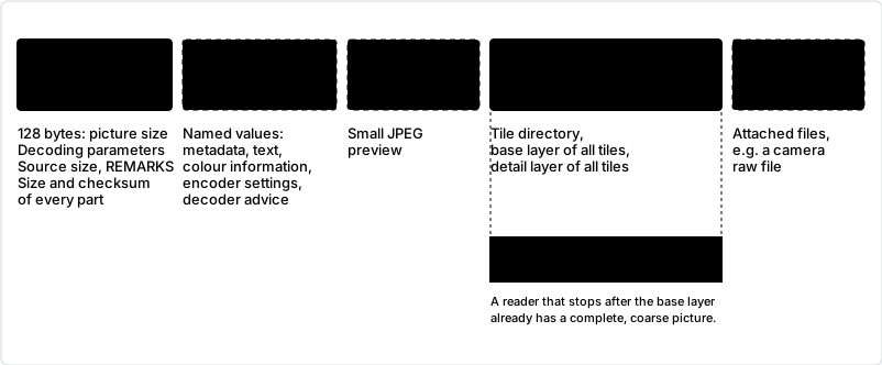
The parts of a FIF2 file. Parts with a dashed outline exist only when they have content. The header states the size of every part, so a reader can find each one without searching.
A program reads a FIF2 file in three steps:
- Header. It checks the first four bytes,
FIF2, and the header checksum. The header gives the picture size, every parameter the decoder needs, and the size of each following part. - Optional parts. It can read the chunks for metadata, show a thumbnail while the picture loads, or ignore both.
- Picture. It decodes the FIC data, tile by tile. If the file ends early, it decodes what is there.
Three properties shape the design:
- Nothing optional is needed to decode the picture. A reader may skip the chunks, the thumbnails and the raw data and still produce the exact picture.
- A shorter file is still a valid file. The picture data is ordered from coarse to fine. Cutting a file anywhere after the header gives a lower-quality picture, not an error.
- The format can be extended. New information goes into new chunk types – including types of a writer's own – or into reserved header fields. Older readers skip what they do not know.
The rest of this document is normative. Section 1 defines conventions. The sections after it form three parts:
- Part I, Container (sections 2 to 7): the sections of the file in the order in which they are stored.
- Part II, FIC bitstream (sections 8 to 10): how the bytes of the FIC data section are decoded into a picture.
- Part III, Checks and versions (sections 11 to 13): rules that apply to the whole file, and an example.
1. Conventions
1.1 Requirement words
must and must not state requirements. A file or a program that does not meet a requirement does not conform to this specification. should states a recommendation. may states a permission.
1.2 Terms
- Reader
- A program that reads FIF2 files. A decoder is a reader.
- Writer
- A program that writes FIF2 files. An encoder is a writer.
- Section
- One of the five parts of a file: header, chunks, thumbnails, FIC data, raw data.
- Plane
- One colour component: Y (luma), Cb or Cr.
- Range block, leaf
- A square block of a plane that the code describes. A leaf is a range block that is not divided further.
- Domain block
- A square region twice as wide as a range block, in the same tile and plane, from which the range block is copied.
1.3 Data types
All multi-byte integers are little-endian. There is no padding and no alignment.
| Type | Encoding |
|---|---|
u8, u16, u32, u64 | Unsigned integer, 1, 2, 4 or 8 bytes, little-endian |
f32, f64 | IEEE 754 binary32 or binary64, stored as u32 or u64 |
char[n] | n bytes of ASCII, no terminator |
utf8 | UTF-8 text, no terminator; its length is stored separately |
varint | Unsigned LEB128 (see 1.4) |
1.4 varint
A varint stores an unsigned integer in groups of 7 bits, least significant group first. Bit 7 of each byte is set when another byte follows.
while (x >= 0x80) { emit((x & 0x7F) | 0x80); x >>= 7; }
emit(x);
A reader must stop after 10 bytes. If the tenth byte has bit 7 set, the file is invalid.
1.5 CRC-32
All checksums are CRC-32 as used by zlib and PNG: reflected polynomial
0xEDB88320, initial value 0xFFFFFFFF, final XOR
0xFFFFFFFF.
Part I
Container
Sections 2 to 7 describe the sections of the file in the order in which they are stored. Section 6 defines where the FIC data is and how it is divided into tiles. Part II defines how its bytes are decoded.
2. File structure
A file consists of these sections, in this order:
header | chunks | thumbnail | FIC data | raw dataThe header states the size of each other section. A size of 0 means that the section is not present; it then occupies no bytes. Sections have no stored offsets. Each section starts where the previous one ends:
chunks_offset    = 128
thumbnail_offset = chunks_offset    + chunk_size
fic_offset       = thumbnail_offset + thumbnail_size
raw_offset       = fic_offset       + fic_size
end_of_file      = raw_offset       + raw_size
A reader must compute these offsets with checks against overflow and against the buffer length.
A buffer that is shorter than end_of_file is a
truncated file. A truncated file is not invalid. Section 6.4 defines how
a reader decodes it.
2.1 Compressed and encrypted sections
Each section after the header may be stored compressed. The compression byte of the header (3) has two bits per section: one says that the section is compressed, the other that it is also encrypted.
A compressed section must be unpacked before anything in it is read: the bytes the header locates as the section, by its position and size, are unpacked first. All structures and rules of this specification then apply to the unpacked section.
The encrypted bit may only be set together with the compressed bit. When it is set, a password is needed to unpack the section.
All CRC values in the header refer to the unpacked content of their section.
Compression can also serve as password protection, and it does so per section. For example, a file may encrypt only its raw section: anyone can then view the picture, but only the holder of the password can extract the original files.
3. Header
The header is always 128 bytes long and has no variable part. The chunk section therefore always starts at offset 128, and a reader can fetch the whole header with one read of 128 bytes. All fields are aligned to their size.
| Offset | Size | Field | Type | Content and requirements |
|---|---|---|---|---|
| 0x00 | 4 | Magic | char[4] | FIF2 |
| 0x04 | 1 | Major version | u8 | 3. A reader must reject any other value. |
| 0x05 | 1 | Minor version | u8 | 1. A reader must reject 0 and accept any higher value (see 12). |
| 0x06 | 1 | Compression | u8 | Bit field, see 2.1. Bit 0: chunks compressed. Bit 1: chunks encrypted. Bit 2: thumbnails compressed. Bit 3: thumbnails encrypted. Bit 4: FIC data compressed. Bit 5: FIC data encrypted. Bit 6: raw data compressed. Bit 7: raw data encrypted. A reader must reject a file in which an encrypted bit is set without the compressed bit of the same section. |
| 0x07 | 1 | Reserved | u8 | 0. A reader must ignore it. |
| 0x08 | 8 | File size | u64 | 128 plus the sizes of all sections. |
| 0x10 | 4 | Width | u32 | Coded width in pixels, 1 to 2^20. |
| 0x14 | 4 | Height | u32 | Coded height in pixels, 1 to 2^20. |
| 0x18 | 1 | Bits per channel | u8 | 8. |
| 0x19 | 1 | Colour model | u8 | 0 = grey: one plane (Y), one output channel. 3 = YCbCr: three planes, RGB output. 1 and 2 are reserved. |
| 0x1A | 1 | Subsampling | u8 | YCbCr only: 0 = 4:4:4, 1 = 4:2:0. Grey: 0, ignored by readers. |
| 0x1B | 1 | Chroma mode | u8 | YCbCr only: 0 = shared, 1 = from luma (see 9.4). Grey: 0, ignored by readers. |
| 0x1C | 1 | dc_bits | u8 | 1 to 12. |
| 0x1D | 1 | s_bits | u8 | 1 to 7. |
| 0x1E | 1 | domain_shift | u8 | 0 to 4. |
| 0x1F | 1 | Coding flags | u8 | Bit 0: planar mode. Bits 1–7: 0. |
| 0x20 | 2 | min_block | u16 | Power of two, at least 2. |
| 0x22 | 2 | max_block | u16 | Power of two, at most 256, at least min_block. |
| 0x24 | 4 | Tile size | u32 | Greater than 0. |
| 0x28 | 8 | Detail offset | u64 | Position where the detail layers begin in the FIC data, relative to the start of the (unpacked) FIC section: the length of the directory plus all base layers (6.1). 0 if the FIC section is absent. |
| 0x30 | 4 | Source width | u32 | Width of the original picture before any reduction. 0 = unknown. |
| 0x34 | 4 | Source height | u32 | As source width. |
| 0x38 | 8 | Source scale | f64 | Factor by which the original was reduced before encoding. 1 = not reduced. A reader must treat a value that is not finite or not positive as 1. |
| 0x40 | 4 | Thumbnail count | u32 | Number of thumbnails. Informative; the count in the thumbnail section (5) applies. |
| 0x44 | 4 | REMARKS | char[4] | Four characters free for any use, see below. Four zero bytes = no remark. |
| 0x48 | 4 | Chunk count | u32 | Number of chunks. Informative. |
| 0x4C | 4 | Chunk CRC | u32 | CRC-32 of the unpacked chunk section (2.1). 0 if absent. |
| 0x50 | 8 | Chunk section size | u64 | As stored. |
| 0x58 | 8 | Thumbnail section size | u64 | As stored. 0 = no thumbnails. |
| 0x60 | 8 | FIC section size | u64 | As stored. Unpacked, at least 2 × the tile count (6.2). |
| 0x68 | 8 | Raw section size | u64 | As stored. 0 = no raw data. |
| 0x70 | 4 | Thumbnail CRC | u32 | CRC-32 of the unpacked thumbnail section. 0 if absent. |
| 0x74 | 4 | FIC CRC | u32 | CRC-32 of the unpacked FIC section. |
| 0x78 | 4 | Raw CRC | u32 | CRC-32 of the unpacked raw section. 0 if absent. |
| 0x7C | 4 | Header CRC | u32 | CRC-32 of bytes 0x00 to 0x7B. |
REMARKS. The field belongs to whoever processes the file. A decoder,
viewer or archive tool from a third party may use it to mark a file – that it
has checked it, converted it, or anything else it needs to recognise later.
The reference encoder writes four zero bytes unless asked otherwise
(fif encode --remarks). A reader must not derive
anything about decoding from it. A tool that changes the field
must recompute the header CRC. The name of the original file, which
earlier drafts kept in the header, is the chunk ENCO source_name
(4.3).
A reader must reject the file when the magic, the major version, the header CRC or any range stated above is wrong. The header contains every value that decoding needs; no chunk is required.
The colour model alone determines the number of planes and of output channels. There is no separate channel count, and a greyscale picture has no subsampling.
4. Chunks
The chunk section is a sequence of chunks without separators. Each chunk holds one named value. A file may contain any number of chunks of the same type. The section may be stored compressed (2.1); this section describes it unpacked.
| Offset | Size | Field | Type | Content |
|---|---|---|---|---|
| 0 | 4 | Type | char[4] | See 4.2. |
| 4 | 1 | Value type | u8 | See 4.1. |
| 5 | 2 | Name length | u16 | n. |
| 7 | n | Name | utf8 | |
| 7+n | 8 | Data length | u64 | m. |
| 15+n | m | Data | The value. | |
| 15+n+m | 4 | CRC | u32 | CRC-32 of all preceding bytes of this chunk, from Type to the end of Data. |
4.1 Value types
| Value | Meaning | Data length |
|---|---|---|
| 0 | Binary | Any |
| 1 | Unsigned integer, little-endian | 1, 2, 4 or 8 |
| 2 | Signed integer, two's complement, little-endian | 1, 2, 4 or 8 |
| 3 | IEEE 754 floating point, little-endian | 4 or 8 |
| 4 | UTF-8 text, no terminator | Any |
4.2 Chunk types
| Type | Purpose |
|---|---|
META | Metadata, for example author or capture date |
TEXT | Free text, for example a copyright notice |
COLR | Colour information, ICC profile |
ENCO | Encoder settings that decoding does not need |
DECO | Recommendations for the decoder |
EXTN | Extensions |
MISC | Anything else: information that fits none of the types above |
The list is not closed. A writer may use a type of its own – any four characters, padded with spaces – to store information that only its own decoder understands, such as decoder-specific hints or processing history. Such a type should not be one of the types above, and should be distinctive enough not to clash with another writer's, for example the first letters of the product. Every other reader skips it (4.4), so a private type never makes a file unreadable.
4.3 Defined chunks
| Type | Name | Value type | Meaning |
|---|---|---|---|
ENCO | encoder | text | Name and version of the encoder |
ENCO | source_name | text | File name of the original picture, without directory |
ENCO | credits | text | Authors of encoder and format and where to read more, as lines separated by LF (see below) |
ENCO | quality | uint | Quality setting, 0 to 100 |
ENCO | effort | uint | Effort setting, 0 to 9 |
COLR | transfer | text | Transfer function of the source, e.g. sRGB |
COLR | primaries | text | Colour primaries of the source, e.g. sRGB |
DECO | deblock | uint | Recommended deblocking strength, 0 to 100 |
DECO | iterations | uint | Recommended maximum number of iterations. 0 = no recommendation. |
DECO | epsilon | float | Recommended convergence threshold in grey levels. 0 = no recommendation. |
META | camera_make | text | Maker of the camera |
META | camera_model | text | Camera model |
META | lens | text | Lens model |
META | date_taken | text | Time the picture was taken, ISO 8601, e.g. 2024-05-01T14:03:22+02:00 |
META | exposure_time | text | Exposure time in seconds, e.g. 1/250 |
META | f_number | float | Aperture, e.g. 2.8 |
META | iso | uint | ISO sensitivity |
META | focal_length | float | Focal length in mm |
META | focal_35mm | uint | Focal length in mm, 35 mm equivalent |
META | author | text | Author of the picture |
META | software | text | Software that last edited the picture |
TEXT | copyright | text | Copyright notice |
TEXT | description | text | Description of the picture |
4.4 Rules for readers
- A reader must skip chunks with an unknown type, an unknown name or an unexpected value type.
- A reader must ignore a chunk whose CRC does not match. A bad chunk must not cause the decode to fail.
- The order of chunks has no meaning. When a
DECOname occurs more than once, the last valid occurrence applies. - For each decoder setting the precedence is: first the value given by the user of the decoder, then the
DECOvalue in the file, then the decoder's default. A value of 0 at the first two levels means “not set” and passes the decision to the next level. - The reference decoder's defaults are: deblocking 0, iterations 16, epsilon 0.5.
- A writer should write a
DECOchunk only for a real recommendation. The reference encoder writesdeblockand omitsiterationsandepsilon. - The reference encoder writes
ENCO creditsby default (about 130 bytes);fif encode --no-creditsleaves it out. Its text has three lines:libfif v3.2 - (c) 2026 Oskar Behzadpour/FIF2 format v3.1 by Rezar Behzad/www.FractalImageCompression.com. - The
METAandTEXTnames above are the ones the reference encoder takes over from the EXIF block of a JPEG or PNG source. Other writers should use the same names for the same information. The GPS position is not taken over. EXIF orientation is applied to the pixels before encoding, so a FIF2 picture is always stored upright and there is no orientation chunk.
5. Thumbnails
The thumbnail section holds any number of thumbnails. Each thumbnail is a complete image file, stored unchanged. Thumbnails may differ in size, format and aspect ratio. The section starts with a count and a directory, followed by the files in directory order without gaps:
count | entry 0 | … | entry count−1 | file 0 | … | file count−1| Offset | Size | Field | Type | Content |
|---|---|---|---|---|
| 0 | 4 | Count | u32 | Number of directory entries. |
| 4 | … | Directory | Count entries, as below. |
One directory entry:
| Offset | Size | Field | Type | Content |
|---|---|---|---|---|
| 0 | 2 | Entry length | u16 | e. Length of this entry in bytes, this field included. 26 in version 3.1; at least 26. |
| 2 | 4 | Format | char[4] | Format code of the file, see below. |
| 6 | 4 | Width | u32 | Width in pixels. 0 = not stated. |
| 10 | 4 | Height | u32 | Height in pixels. 0 = not stated. |
| 14 | 8 | Data size | u64 | Size of the file. |
| 22 | 4 | Data CRC | u32 | CRC-32 of the file. |
| 26 | e−26 | Reserved | Empty in version 3.1. A reader must skip these bytes. |
File i starts at the end of the directory plus the data sizes of files 0 to i−1. A reader can therefore read the count and the directory, choose one thumbnail, and fetch only that file.
| Format code | Content |
|---|---|
JPEG | A JPEG (JFIF) file. |
| other | Reserved for later formats, e.g. PNG␣, WEBP, AVIF. A new format needs only a new code; the container does not change. |
- A reader must reject the thumbnail section, but not the file, when the directory or the data sizes do not fit in the section size.
- The width and height in the directory are a hint. When they disagree with the image file, the image file is authoritative.
- A writer should list thumbnails by increasing size, so that a reader that stops early has the smallest ones. A reader must not depend on the order.
- A reader that does not know a format code must ignore that thumbnail and may use the others.
- A reader should ignore a thumbnail whose data CRC does not match.
- Thumbnails have no effect on the decoded picture.
6. FIC data
6.1 Layout
| Part | Size | Content |
|---|---|---|
| directory | variable | For each tile i = 0 … N−1 in tile order: varint base_len[i], varint detail_len[i]. N is the tile count computed in 6.2. |
| base run | Σ base_len | The base layer of tile 0, then of tile 1, …, then of tile N−1. |
| detail run | Σ detail_len | The detail layer of tile 0, then of tile 1, …, then of tile N−1. |
Byte position of the layers of tile i, relative to the start of
the FIC section, with D the length of the directory:
base(i)   = D + base_len[0] + … + base_len[i−1]
detail(i) = D + Σ base_len + detail_len[0] + … + detail_len[i−1]
Each layer is one independent range-coded stream (8). The base layer holds the quadtree, the mode bits, the DC values and the planar flags. The detail layer holds everything else. Because all base layers come before all detail layers, every prefix of the section is decodable (6.4).
The header field detail offset (3) states where the detail run begins:
D + Σ base_len. A reader may read and decode only the first
detail-offset bytes of the FIC data and so produce the coarse picture alone,
without the fractal detail – for a quick preview, or to fetch less of a file
over a network. The detail offset must equal the value computed from the
directory; a reader must reject a file in which it does not.
6.1.1 Order of symbols in one tile
The decoder reads both layers of a tile in one pass over the leaves. Each symbol comes from its own layer; within each layer, the symbols appear in the order of this pass. The table lists the pass for a tile in chroma mode shared.
| Step | Base layer | Detail layer |
|---|---|---|
Luma plane Y: roots of edge max_block in raster order, each node in pre-order (9.2) | ||
| inner node | split flag = 1 | — |
| leaf | split flag = 0 (only if edge > min_block) mode bit (if a domain grid exists) DC residual planar flag (if mode 0 and planar mode on) | if planar: gx, gy if fractal: dx, dy or uniform gx, gy if fractal: symmetry if fractal: contrast |
| Chroma plane Cb: one leaf per luma leaf, in the order of the luma leaves; no split flags | ||
| leaf | mode bit (if the luma leaf's mode bit is 1) DC residual planar flag (if mode 0 and planar mode on) | if planar: gx, gy if fractal: contrast |
| Chroma plane Cr: as Cb |
Differences in the other cases:
- Chroma mode from luma: every chroma leaf codes its mode bit. The detail layer is the same as in shared mode.
- Greyscale: only the luma plane.
- Detail layer missing: the base layer is read in the same order; the detail symbols are skipped (9.3).
Example: a luma root of edge 32, split once, whose top-left child is a
fractal leaf and whose other three children are flat, not planar leaves
(min_block 4):
| # | Base layer | Detail layer |
|---|---|---|
| 1 | split = 1 (root, 32) | |
| 2 | split = 0, mode = 1, DC (child 0, 16) | dx, dy, symmetry, contrast |
| 3 | split = 0, mode = 0, DC, planar = 0 (child 1) | |
| 4 | split = 0, mode = 0, DC, planar = 0 (child 2) | |
| 5 | split = 0, mode = 0, DC, planar = 0 (child 3) |
6.2 Tile geometry
Tile positions and sizes are not stored. The reader computes them:
cs    = (colour model == grey) ? 0 : (subsampling == 4:2:0 ? 1 : 0)
align = max_block << cs
pw    = round_up(width,  align)          // padded width
ph    = round_up(height, align)          // padded height
ts    = max(align, round_up(tile_size, align))
tiles: raster order over (pw, ph) with step ts; the last tile in each row and
       column is clipped to pw and ph
The number of tiles is not stored; it follows from this computation. The
pixels beyond width and
height are padding. The writer fills them by repeating the last
row and column. The reader discards them.
6.3 Planes within a tile
A tile of size tw × th has a luma plane of that size. With
4:2:0 subsampling its chroma planes are (tw/2) × (th/2); with
4:4:4 they are tw × th; with 4:0:0 there are none.
6.4 Truncated files
A reader must handle a short FIC section as follows. These cases are not errors.
- The available FIC bytes are the declared size limited to the end of the buffer. The header, chunks and thumbnails must be complete. For a compressed FIC section, the available bytes are what the available part unpacks to.
- If the base layers are not complete for all tiles, the reader decodes the tiles whose base layer is complete. It fills the other tiles with the value 128.
- If the detail layer of a tile is missing, the reader decodes every leaf of that tile from its DC value only (see 9.3).
The file is invalid when the range decoder of a base layer reads past the end of that layer.
Part II (sections 8 to 10) defines how each layer is decoded.
7. Raw data
The raw section carries files in other formats alongside the fractal code – the camera raw file, the original JPEG and the like. It starts with a count, followed by the entries without gaps. Each entry is a description followed by the file:
count | entry 0 | … | entry count−1| Offset | Size | Field | Type | Content |
|---|---|---|---|---|
| 0 | 4 | Count | u32 | Number of entries. |
| 4 | … | Entries | Count entries, as below. |
One entry:
| Offset | Size | Field | Type | Content |
|---|---|---|---|---|
| 0 | 4 | FileType | char[4] | Kind of file, padded with spaces, e.g. DNG␣, JPEG, TIFF. |
| 4 | 2 | FileName length | u16 | n. |
| 6 | n | FileName | utf8 | Original file name, without directory. |
| 6+n | 8 | FileSize | u64 | Size of the original file. |
| 14+n | 4 | FileCodec | char[4] | How Data is stored. NONE = unchanged. Other values are reserved. |
| 18+n | 4 | Metadata length | u32 | k. |
| 22+n | k | Metadata | utf8 | Free description of the file. |
| 22+n+k | 8 | FileDataSize | u64 | d. Equals FileSize when FileCodec is NONE. |
| 30+n+k | d | Data | The file. |
The whole section may be stored compressed or encrypted (2.1); FileCodec then still describes each file inside the unpacked section. A truncated file may end inside an entry; a reader should report the entries before it and the part of that entry that arrived.
Raw data has no effect on the decoded picture. A reader may ignore it.
Part II
FIC bitstream
Sections 8 to 10 define how one layer of one tile is decoded: the range coder, the order and meaning of the symbols, and the reconstruction of the pixels.
8. Range coder
Each layer is coded with an adaptive binary range coder of the LZMA type.
| Parameter | Value |
|---|---|
| Probability resolution | 11 bits, kProbOne = 2048 |
| Adaptation shift | 5 |
| Renormalisation threshold | 224 |
| Initial range | 0xFFFFFFFF |
8.1 One adaptive bit
The model holds a probability p that the bit is 0.
bound = (range >> 11) * p
bit 0:  range = bound;                      p += (2048 - p) >> 5
bit 1:  code  -= bound;  range -= bound;    p -= p >> 5
then:   while (range < 2^24) { range <<= 8; code = (code << 8) | next_byte }
8.2 Uniform bits
Uniform bits use no model and are read most significant bit first. For each
bit: range >>= 1; the bit is 1 if code >= range,
in which case code -= range; then renormalise as in 8.1.
8.3 Start and end
To start, the decoder reads one byte and discards it, then reads four bytes
most significant first into code. A decoder
must not be started on an empty layer. The encoder
ends a layer by flushing five bytes. There is no end symbol; the length in the
directory ends the layer.
8.4 Bit trees
A symbol from an alphabet of 2k values is coded with a tree of adaptive bits, most significant bit first:
m = 1
repeat k times: m = (m << 1) | decode_bit(probs[m])
symbol = m - (1 << k)
8.5 Signed residuals
DC residuals, domain displacements and gradients use one scheme, an Elias-gamma code with modelled length:
if decode_bit(zero) == 0:  value = 0, stop
neg = decode_bit(sign)
k = 1
while k < MAXLEN and decode_bit(len[k − 1]) == 1:  k = k + 1      // MAXLEN = 18
m = 1 << (k − 1)
if k > 1:  m = m | uniform_bits(k − 1)
value = neg ? −m : m
9. Symbol syntax
9.1 Context models
The decoder creates one set of context models per tile and resets it at the start of every tile. Chroma planes Cb and Cr share their models.
| Model array | Entries | Index |
|---|---|---|
split[2][9][3] | 54 | plane class, level, split context |
mode[2][9][3] | 54 | plane class, level, mode context |
dc_zero[2][9][4] | 72 | plane class, level, activity class |
dc_sign[2][4] | 8 | plane class, activity class |
dc_len[2][4][18] | 144 | plane class, activity class, length position |
dd_zero[2][2], dd_sign[2][2] | 4 + 4 | plane class, component |
dd_len[2][2][18] | 72 | plane class, component, length position |
sym[2][9][8] | 144 | plane class, level, tree node |
planar[2][9][3] | 54 | plane class, level, planar context |
g_zero[2][2], g_sign[2][2] | 4 + 4 | plane class, component |
g_len[2][2][18] | 72 | plane class, component, length position |
contrast[2][9][128] | 2304 | plane class, level, tree node |
| Total | 2994 |
“Plane class” is 0 for luma and 1 for chroma. “Level” is log2 of the block edge.
Initial probabilities. The models do not start at ½. They start from
a fixed table of 2994 values, in the order of the arrays above, that is part of
the codec and is not stored in the file. An independent decoder
must reproduce this table exactly. The table is a
normative part of this specification: for major version 3 it is the file
src/ctxtable.inc of the reference implementation (the C array kDefaultProbs, 2994 unsigned
16-bit values in the order above). It belongs to the major
version and does not change within it (see 12).
Neighbours. For a leaf with top-left pixel (x, y) and
edge n, the neighbours are the leaves that contain the pixels left
(x−1, y), above (x, y−1), above left
(x−1, y−1) and above right (x+n, y−1). Coordinates are
relative to the tile plane.
The decoder keeps one neighbour map per plane. It creates a new, empty map
for the luma plane and for each chroma plane of every tile; Cb does not see the
leaves of Cr and the other way round. A neighbour exists only if its leaf has
already been decoded in the same map and lies inside the tile plane. For each
decoded leaf the map records: its origin and edge, its quantised DC value, its
coded mode bit, its planar flag, and, if it has a transform,
the domain origin in pixels (gx · step, gy · step), the
symmetry and the quantised contrast. A leaf has a transform when it is
fractal and its detail layer was decoded, or when it inherited a transform in a
shared chroma plane.
The level of a block of edge n is the smallest
l with 2l ≥ n, at most 8.
Split, mode and planar contexts are each a count from 0 to 2 over the left and upper neighbours:
| Context | A neighbour counts when |
|---|---|
| split | its edge is smaller than the current node's edge |
| mode | its coded mode bit is 0 |
| planar | its planar flag is 1 |
DC prediction and activity class. Let a, b
and c be the quantised DC values of the left, upper and upper-left
neighbours.
if left and upper exist:
    if upper-left is missing:  c = (a + b + 1) >> 1
    prediction = c ≥ max(a,b) ? min(a,b)
               : c ≤ min(a,b) ? max(a,b)
               : a + b − c                        // JPEG-LS median edge detector
    d     = |a − c| + |b − c|
    unit  = 1 << max(0, dc_bits − 4)
    class = d ≤ unit ? 0 : d ≤ 3·unit ? 1 : d ≤ 8·unit ? 2 : 3
else if only left exists:   prediction = a, class = 0
else if only upper exists:  prediction = b, class = 0
else:                       prediction = 1 << (dc_bits − 1), class = 0
The DC residual is the quantised DC minus the prediction. The decoder
computes q_dc = clamp(prediction + residual, 0, 2^dc_bits − 1).
Domain prediction. Each of the left, upper and upper-right neighbours
that has a transform casts a vote: its domain origin in pixels, moved by the
offset from its range origin to the current range origin. The prediction is
the component-wise median of three votes, the mean (shifted right by one) of
two votes, or the single vote. It is converted to grid indices with
clamp(p / step, 0, g − 1) per axis. When no neighbour votes, no
prediction exists and the position is coded with uniform bits (symbol 6′).
Otherwise the difference between the grid index and the prediction is coded
(symbol 6). The decoder adds the prediction and clamps each index to
0 … gw − 1 and 0 … gh − 1. The domain index is
gy · gw + gx.
9.2 Traversal
Within a tile, the planes are coded one after the other in the order Y, Cb, Cr, in the same two range-coded layers. Each plane is traversed as a quadtree, depth first in pre-order, starting from root blocks in raster order over the tile plane. The children of a split node are visited top left, top right, bottom left, bottom right.
- Luma roots have the edge
max_block. - A chroma plane has no quadtree of its own. It follows the luma quadtree: every luma leaf at
(x, y)with edgengives one chroma leaf at(x >> cs, y >> cs)with edgen >> cs, in the order of the luma leaves. No split flags are coded for these planes.
Because of the padding in 6.2, the width and height of every luma tile
plane are multiples of max_block. Root blocks therefore never
extend past the tile.
9.3 Node syntax
For each node of edge n:
- Split flag (base layer), only when
n > min_block. When it is 1, the node has four children and nothing else is coded for it. - Otherwise the node is a leaf, coded as follows:
| # | Symbol | Layer | Present when |
|---|---|---|---|
| 1 | Mode bit (1 = fractal) | base | Luma: a domain grid exists for this block size (10.1). Chroma mode shared: the luma leaf's mode bit is 1. Chroma mode from luma: always. |
| 2 | DC residual | base | always |
| 3 | Planar flag | base | planar mode is on and the coded mode bit is 0 |
| 4 | Gradients gx, gy (signed residuals) | detail | the planar flag is 1 |
| 6 | Domain displacement dx, dy (signed residuals) | detail | luma only: the leaf is fractal and a prediction exists |
| 6′ | Domain position gx, gy (uniform bits) | detail | as 6, but no prediction exists |
| 7 | Symmetry (3-bit tree) | detail | as 6 or 6′ |
| 8 | Contrast s_q (s_bits-bit tree) | detail | the leaf is fractal |
Models used. Symbol 1 uses mode[pc][level][mode context];
2 uses dc_zero[pc][level][class], dc_sign[pc][class]
and dc_len[pc][class]; 3 uses
planar[pc][level][planar context]; 4 uses g_*[pc][0]
for gx and g_*[pc][1] for gy; 6 uses dd_*[pc][0] for dx and dd_*[pc][1] for dy; 7 uses
sym[pc][level]; 8 uses contrast[pc][level]. The split
flag uses split[pc][level][split context]. pc is 0 for
luma and 1 for chroma.
Limits. The decoder clamps each gradient to
−(4 << dc_bits) … (4 << dc_bits).
Missing detail layer. The mode bit is in the base layer and is always read; it also sets the mode context of later leaves. When the detail layer of a tile is absent, the reader must skip symbols 4 to 8 and treat every leaf as not fractal, without gradient. The result is a complete picture at DC resolution.
Uniform domain positions use bits_for(gw) and
bits_for(gh) bits, the number of bits needed to represent
gw − 1 and gh − 1.
9.4 Chroma modes
The chroma neighbour map uses cmin = max(2, min_block >> cs)
as its cell size.
- shared (0)
- Chroma leaves follow the luma leaves (9.2). A chroma leaf codes its mode bit only when the luma leaf's mode bit is 1; otherwise its mode is 0. It codes DC and planar data as usual, and, when fractal, only its contrast. The domain index and the symmetry are those of the luma leaf. The chroma leaf interprets the luma domain index on its own grid (10.1 with the chroma leaf edge and the chroma tile plane), which has the same number of positions. If the luma leaf has no transform because its detail layer is missing, the chroma leaf has none either.
- from luma (1)
- Chroma leaves follow the luma leaves (9.2). Every chroma leaf codes its mode bit. A fractal chroma leaf codes only its contrast. Its source is the co-located block of the reconstructed luma plane (10.5); no domain or symmetry exists.
With 4:0:0 subsampling there are no chroma planes.
9.5 Symmetries
Source coordinate for target coordinate (x, y) in a block of
edge n:
| Value | Transformation | Source x | Source y |
|---|---|---|---|
| 0 | Identity | x | y |
| 1 | Rotation 90° | y | n−1−x |
| 2 | Rotation 180° | n−1−x | n−1−y |
| 3 | Rotation 270° | n−1−y | x |
| 4 | Mirror in x | n−1−x | y |
| 5 | Transpose | y | x |
| 6 | Mirror in y | x | n−1−y |
| 7 | Anti-transpose | n−1−y | n−1−x |
10. Reconstruction
10.1 Domain grid
For a leaf of edge n in a tile plane of size
tw × th (for chroma, the chroma tile plane of 6.3):
step = max(1, (2·n) >> domain_shift)
gw   = (tw − 2n) / step + 1       (0 if tw < 2n)
gh   = (th − 2n) / step + 1       (0 if th < 2n)
domain origin = (gx · step, gy · step), relative to the tile
When gw or gh is 0, no domain grid exists and the
mode bit is not coded.
10.2 Dequantisation
dc = (q_dc + 0.5) · 255 / 2^dc_bits
s  = 2 · (q_s + 0.5) / 2^s_bits − 1
The contrast therefore lies in (−1, 1), so every map is contractive.
A planar leaf adds a gradient that keeps the block mean equal to
dc:
unit = 255 / 2^dc_bits
ux   = (x + 0.5)/n − 0.5,   uy = (y + 0.5)/n − 0.5
value(x, y) = dc + unit · (gx · ux + gy · uy)
10.3 The transformation
A fractal leaf R is computed from the current reconstruction:
R(x, y) = dc + s · ( D(σg(x, y)) − D̄ )
D is the 2n × 2n domain region, reduced to n × n by averaging each 2 × 2 group of pixels. σg is the symmetry of 9.5 and D̄ the mean of the reduced domain. D is read from the current reconstruction of the same tile and plane, not from the original picture.
A leaf without a transform (mode 0, or fractal without decoded detail, or
without a domain grid) is filled with dc, plus its gradient if it
is planar. A fractal leaf never has a gradient.
10.4 Iteration
- Fill every leaf with its DC value (with its gradient, if planar). This is the starting picture.
- Compute every leaf of the tile from the current picture, using 10.2 and 10.3. All leaves read from the same current picture.
- Stop when the largest change of any sample is smaller than the convergence threshold, or when the maximum number of iterations is reached. Otherwise repeat step 2.
The fixed point does not depend on the starting picture. The starting picture, the threshold and the iteration limit affect only the number of iterations and, when the limit is reached, how close the result is to the fixed point.
With chroma mode from luma, only the luma plane is iterated; the chroma planes are computed once afterwards (10.5).
10.5 Chroma from luma
With chroma mode from luma, after the luma plane of a tile has
converged, each chroma leaf at (x, y) with edge n is
computed as follows:
- A leaf with mode 0 is filled with
dcand its gradient, as in 10.3. - A fractal leaf uses as source L the co-located luma block: with 4:2:0, the 2n × 2n luma block at
(2x, 2y), reduced by 2 × 2 averaging; with 4:4:4, the n × n luma block at(x, y). ThenR(x, y) = dc + s · (L(x, y) − L̄)with the meanL̄of the source. There is no symmetry.
10.6 Colour conversion
At 4:2:0 the chroma planes have half the luma resolution in each
direction; how they are brought up to it is not normative (10.7). Chroma
sample i covers luma samples 2i and
2i+1, so luma coordinate x corresponds to chroma
coordinate (x − 0.5)/2. The conversion to RGB is full-range
BT.601 as in JPEG:
R = Y + 1.402    · (Cr − 128)
G = Y − 0.344136 · (Cb − 128) − 0.714136 · (Cr − 128)
B = Y + 1.772    · (Cb − 128)
Each result is rounded to the nearest integer and clamped to 0 to 255. A
greyscale file has only Y. The output is cropped to width × height.
10.7 Not normative
Everything a decoder does to the attractor after it has converged – and
the seam filter it may also run inside the last iterations – is its own
choice. The format does not define it, so two conforming decoders may produce
slightly different pictures from the same file, and a better decoder improves
old files without a new encode. The DECO chunks are
recommendations only.
- Chroma upsampling. The reference upsampling is bilinear on the grid of 10.6, clamped to the plane. A decoder may use another method. The reference decoder by default adds to the bilinear chroma the luma detail the chroma grid cannot carry, scaled by the local slope of chroma over luma (a guided filter); colour edges then follow the brightness edges.
- Deblocking. A decoder may filter block seams. The reference decoder uses the quadtree: it knows where every seam is, how large the blocks on either side are and whether they are flat, planar or fractal. Seams between smooth blocks are ramped widely, seams in texture barely touched, and steps too large for quantisation are left as edges. Its strength comes from
DECO deblock. - Smooth flat blocks. A decoder may bend flat and planar blocks so that they meet their smooth neighbours at the corners, keeping each block's mean. The reference decoder does so by default.
- Dithering. A decoder may dither when it rounds to 8 bits.
- Scale. A decoder may reconstruct at a larger or smaller scale by multiplying all positions and sizes.
Part III
Checks and versions
Sections 11 to 13 apply to the whole file.
11. Integrity
| Checksum | Covers | When it does not match |
|---|---|---|
| Header CRC | Bytes 0x00 to 0x7B | The reader must reject the file. |
| Chunk section CRC | The unpacked chunk section | The reader should warn. It may still read the chunks: each one carries its own CRC. |
| Chunk CRC | The whole chunk, type to end of data | The reader must ignore the chunk. |
| Thumbnail CRC | The unpacked thumbnail section | The reader should warn. |
| Data CRC of a thumbnail | One thumbnail file | The reader should ignore that thumbnail. |
| FIC CRC | The unpacked FIC section | The reader should warn and may decode. |
| Raw CRC | The unpacked raw section | The reader should warn. |
The section CRCs in the header always refer to the unpacked content (2.1). A compressed or encrypted section can therefore only be checked after it has been unpacked.
A reader checks a section CRC only when the section is complete. Tiles are independent, so damage in the FIC section affects only the tiles it touches. The reference decoder therefore decodes a file with a bad FIC CRC and reports the mismatch separately.
In all cases a reader must check every length against the remaining buffer before it uses the length, and must limit the number of pixels it allocates. The reference decoder refuses pictures of more than 2^28 pixels unless the user raises the limit.
12. Versions
- A reader must reject a file whose major version is not 3, and a file with version 3.0. Files with a lower version were written by development versions, use other layouts and are not supported. Version 3.1 is the first published version of the format.
- The header has a fixed size of 128 bytes in every 3.x version. A later minor version may give a meaning to the reserved byte at 0x07 and to the unused coding-flag bits, add fields at the end of a thumbnail directory entry, and add chunk types and names, thumbnail formats and raw codecs. Information that does not fit there goes into chunks. A minor version must not change the context models or their initial probability table (9.1); such a change requires a new major version. It must not change the meaning of an existing field.
- The magic
FIF2names the format, not the container version.
13. Example
The start of a 32 × 32 greyscale file named a.pgm, one tile, no
thumbnail, no raw data. xx marks bytes that depend on the
content.
0x0000  46 49 46 32                 "FIF2"
0x0004  03 01                       version 3.1
0x0006  00                          compression: no section compressed
0x0007  00                          reserved
0x0008  A2 02 00 00 00 00 00 00     file size 674
0x0010  20 00 00 00  20 00 00 00    width 32, height 32
0x0018  08 00                       8 bits, colour model grey
0x001A  00 00                       subsampling, chroma mode: unused for grey
0x001C  08 06 02                    dc_bits 8, s_bits 6, domain_shift 2
0x001F  01                          coding flags: planar mode on
0x0020  04 00  20 00                min_block 4, max_block 32
0x0024  00 01 00 00                 tile size 256: one tile
0x0028  49 00 00 00 00 00 00 00     detail offset 73
0x0030  20 00 00 00  20 00 00 00    source size 32 × 32
0x0038  00 00 00 00 00 00 F0 3F     source scale 1.0
0x0040  00 00 00 00                 0 thumbnails
0x0044  00 00 00 00                 REMARKS: none
0x0048  08 00 00 00  xx xx xx xx    8 chunks, chunk section CRC
0x0050  59 01 00 00 00 00 00 00     chunk section size 345
0x0058  00 …                        thumbnail section size 0: absent
0x0060  C9 00 00 00 00 00 00 00     FIC section size 201
0x0068  00 …                        raw section size 0: absent
0x0070  00 00 00 00  xx xx xx xx  00 00 00 00    CRCs: thumbnail, FIC, raw
0x007C  xx xx xx xx                 header CRC
0x0080  45 4E 43 4F  04             chunk "ENCO", value type text
        07 00  65 6E 63 6F 64 65 72                 name "encoder"
        0B 00 00 00 00 00 00 00                     data length 11
        6C 69 62 66 69 66 20 76 33 2E 32            "libfif v3.2"
        xx xx xx xx                                 chunk CRC
0x00A5  45 4E 43 4F  04             chunk "ENCO", value type text
        0B 00  73 6F 75 72 63 65 5F 6E 61 6D 65     name "source_name"
        05 00 00 00 00 00 00 00                     data length 5
        61 2E 70 67 6D                              "a.pgm"
        xx xx xx xx                                 chunk CRC
        …                           six further chunks (4.3)
0x01D9  46  80 01                   FIC directory: base 70 bytes, detail 128 bytes
0x01DC  [70 bytes]                  base layer of tile 0
0x0222  [128 bytes]                 detail layer of tile 0, at detail offset
                                    3 + 70 = 73; ends at 0x02A2 = 674